How the lawn mower walking system works
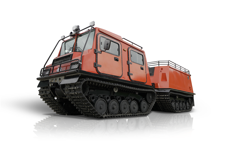
Tracked Utility Terrain Vehicle-Fire truck

On the basis of the personnel carrier, the fire-fighting vehicle designs a sprinkler device for the rear vehicle, adopts the integrated structure of the carport water tank, and installs a fire-fighting water pump and a high-pressure energy-saving cleaning pump. The fire-fighting water pump can continuously spray water for 15 minutes under high pressure, and the high-pressure energy-saving water pump can continuously spray water for more than 1.5 hours to achieve fire extinguishing operations while driving. The fire pump and the high-pressure energy-saving cleaning water pump can be operated separately at the same time.
This lever changes the steering force of the mower, thereby altering the course of the machine. This lever is located near the left and right upper control handles, respectively.A self-propelled walk-behind lawn mower walking system includes a speed control assembly, a casing, and a pair of levers that are selectively coupled to the engine through a belt. The speed engagement assembly comprises a first lever that is rotatable, and a second lever that is attached to the casing. The speed control assembly includes a knob that is operatively connected to the first and second levers.A self-propelled lawn mower walking system can be equipped with a lever control 90 to operate the drive transmission to the rear wheels. In contrast to the traditional self-propelled mower, this self-propelled lawn mower walking system is self-propelled, which makes maneuverability and avoiding obstacles difficult.
A lawn mower walking system includes a control assembly that's attached to the rear portion of the mower body. The rear portion is composed of a rear cross portion and opposing side portions. In addition to the handle, the control assembly includes two curved bale members that are pivotally connected between the side portions. These bale members are connected to a first control cable that connects them to the operator zone engine kill/restart assembly and a second control cable that connects the pivotable bale member to the wheel clutch. The bale members may be positioned in any of the two positions for the mower to stop, go back to a standstill, or perform other functions.Another important aspect of the control mechanism is compliance with federal safety standards.
Federal regulations require separate means for engaging the wheel clutch and engine kill/restart controls. In some designs, the two controls are actuated simultaneously. Alternatively, the wheel clutch is engaged when the mower is in the neutral position. The resulting system prevents the operator from accidentally engaging the cutting blades of the lawn mower.One embodiment of a lawn mower walking system comprises a frame 210 configured to flex in response to an applied force. The frame may include a conventional shock absorber system, such as springs and struts, and it may also comprise a linkage. The flexing action of the frame may result in a suspension travel of about 2 centimeters or more, which may provide improved operator comfort and reduced shock transfer to the rider.


 浙ICP备2022029871号